Alignment marks
Marker Block & Faraday Cup
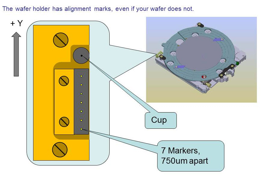
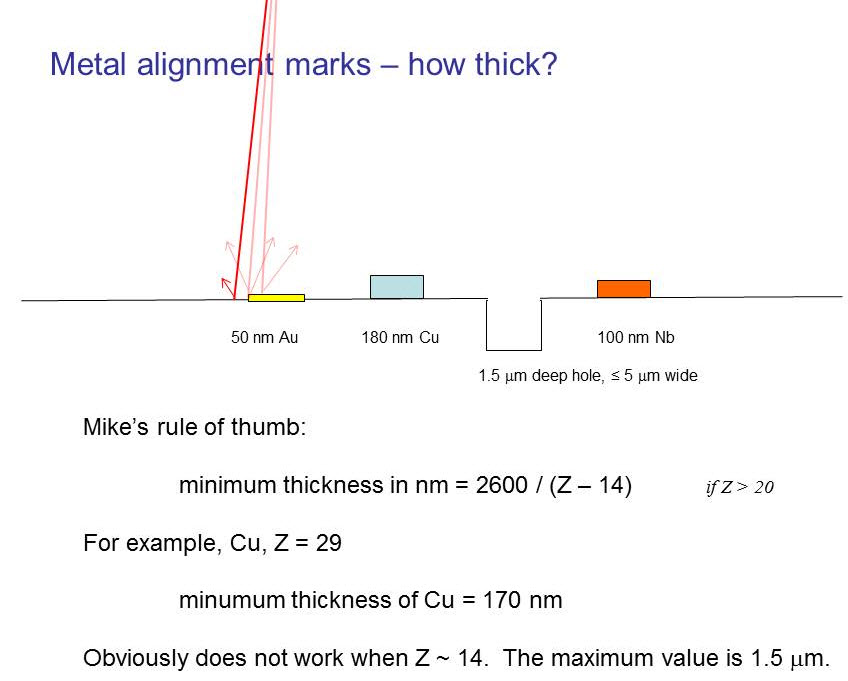
Gold marks on the reference block allow the system to calibrate beam deflection and distortion. The Faraday cup is used for measuring beam current. It is simply a hole from which secondary electrons cannot escape. Do you know who Michael Faraday was? Better look him up, and then ANSWER THIS QUESTION. The positions of markers and Faraday cups are stored in the EBPG, so you need only indicate which sample chuck you are using.
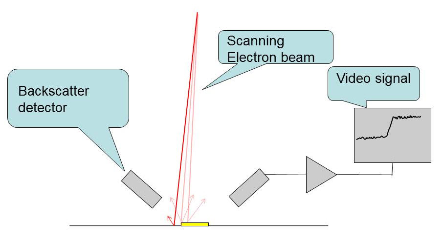
What is a marker?
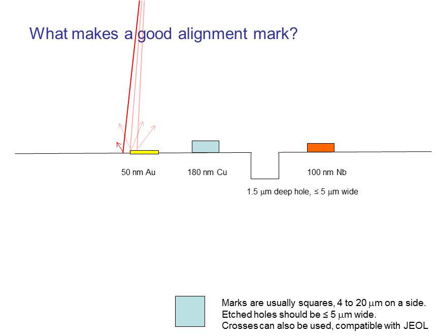
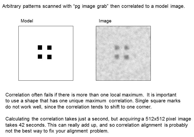
What else can be used as an alignment mark?
Strange alignment mark example: silicon nitride windows
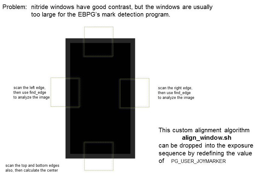
Here is a case where both standard alignment and correlation alignment fail. Silicon nitride windows provide high contrast “marks” but these windows are usually larger than 100 um, the maximum mark size on the EBPG. Instead of using standard mark detection, we collect images of each side, then analyze these images with “find_edge”. The sequence is defined in a script (align_window.sh) that you can plug into an exposure job.
Alternatively, the EBPG has an imprecise alignment mode in which the operator simply points to a location to indicate where the “mark” is. This type of marker is called “joy” for the use of a virtual “joystick”. You don’t know what a joystick is? Don’t worry, it won’t be on the test.
This is the test: THE CRUEL WORLD OF ALIGNMENT MARKS. Yes, you have to answer these questions.
Computer Aided Design
Computer aided design (CAD) programs help you design patterns, then produce output in a standard interchange format. Those CAD files can then be converted to a machine-specific format for (say) e-beam patterning. Many CAD programs produce the output format GDSII, also known as “GDS”. This is the most common file standard for electron-beam lithography and photolithography. A more modern format is “Oasis”, which few people use even though it’s probably fine. Good CAD programs which produce valid GDS format include
Layout, from Juspertor UG (we have a site license for this)
Design Workshop
LEdit, from Tanner
These are not free. A simple free CAD program that might fulfill modest needs is
Free CAD programs to avoid include
Kik
Vem
Magic
The CAD tools from Cadence are fantastic for designing integrated circuits, but are not so great at simple geometrical editing. Try your best to avoid Cadence. Common, general-purpose CAD programs such as AutoCAD and DesignCAD can also be used for e-beam lithography, but their output format is a problem. AutoCAD and DesignCAD produce DXF format, for which there are various non-standard interpretations. Lack of standardization is a good reason to avoid these programs. On the other hand, DesignCAD does have a nice facility for designing around photos, so that might be a reason to suffer with compatibility problems.
Some people write their own programs for generating patterns, or use a combination of manual design and algorithmic design. Writing such programs is easy when you use the GDS libraries for C, Python, or Matlab. Alternatively, a pattern-generating program could spit out the simple text format CIF, which can be read into the CAD programs listed above. Beware: Some CAD programs have internal ‘macro’ languages which are tempting, but such captive programs are very slow and very non-portable. The common term for these macros is “paramatrized cells” or “p-cells”. Macro systems are designed to trap you into one particular CAD program, so don’t be fooled.
Much more information about CAD can be found in the Layout CAD Tutorial.
Next, we will look at the big picture; that is, the overall work flow from design to exposure.
CAD design
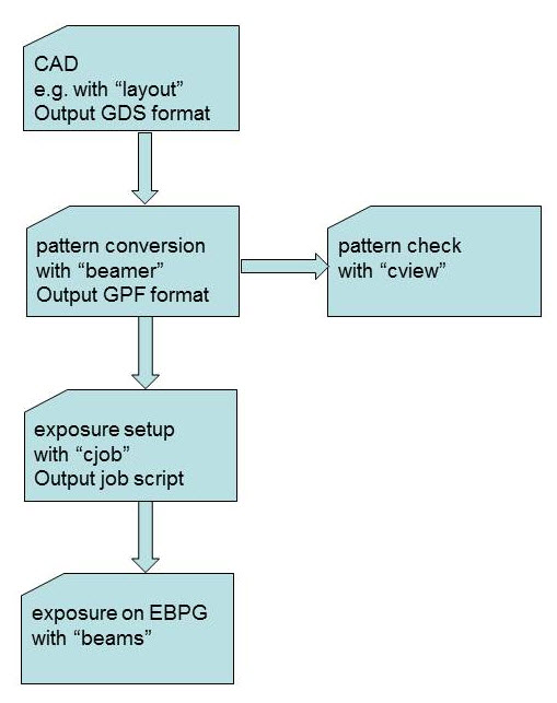
Starting at the top, you will want to work through the Layout CAD Tutorial. Layout (and other CAD programs) produce GDS format pattern files. It is possible to use other pattern formats, such as DXF and CIF, but it’s best to stay with GDS since it is the most stable, standardized, and fully functional. GDS is also known as “GDSII” and “Calma”.
